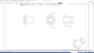
Media Summary: Looking at some of the Advanced Modelling functionality in Remove the constraints of traditional CAD. The model is selected from '3D Sync Test drive' E-Book. This tutorial provides instructions for

Solid Edge St9 Build A - Detailed Analysis & Overview

Looking at some of the Advanced Modelling functionality in Remove the constraints of traditional CAD. The model is selected from '3D Sync Test drive' E-Book. This tutorial provides instructions for New Blog by Application Engineer Dylan Malak. The topic for today is using Welcome to another edition of the PROLIM PLM To draw the 3D Part as per the 2D Dimensions using

Flexible Licensing options now available. Subscription Options: Synchronous technology continues to be a game changer in 3D product development;

Photo Gallery

SOLID EDGE ST9 - ADVANCED MODELLING
Solid Edge ST9 - Sheet Metal
What's New in Solid Edge ST9: 3D Modeling
Building a Roller Assembly ‘Solid Edge ST9’
Solid Edge ST9 Create Section View
Solid Edge ST9 - Adjustable part
Solid Edge ST9 - Build a Mold Around an Existing Tool
What's New in Solid Edge ST9 (Part 1)? - Tutorial - PROLIM LunchByte
Nut and Bolt Design in SOLID EDGE ST9
Solid Edge ST9 - First Look Webinar
3D Part Drawing Using SOLID EDGE ST9 Software
Screw Jack Parts and  Assembly (Bottle Type) By using Solid Edge ST9
Sponsored
Sponsored
View Detailed Profile
SOLID EDGE ST9 - ADVANCED MODELLING

SOLID EDGE ST9 - ADVANCED MODELLING

Looking at some of the Advanced Modelling functionality in

Solid Edge ST9 - Sheet Metal

Solid Edge ST9 - Sheet Metal

... all the corners to fill it

Sponsored
What's New in Solid Edge ST9: 3D Modeling

What's New in Solid Edge ST9: 3D Modeling

Remove the constraints of traditional CAD.

Building a Roller Assembly ‘Solid Edge ST9’

Building a Roller Assembly ‘Solid Edge ST9’

The model is selected from '3D Sync Test drive' E-Book. This tutorial provides instructions for

Solid Edge ST9 Create Section View

Solid Edge ST9 Create Section View

How to

Sponsored
Solid Edge ST9 - Adjustable part

Solid Edge ST9 - Adjustable part

Leírás.

Solid Edge ST9 - Build a Mold Around an Existing Tool

Solid Edge ST9 - Build a Mold Around an Existing Tool

New Blog by Application Engineer Dylan Malak. The topic for today is using

What's New in Solid Edge ST9 (Part 1)? - Tutorial - PROLIM LunchByte

What's New in Solid Edge ST9 (Part 1)? - Tutorial - PROLIM LunchByte

Welcome to another edition of the PROLIM PLM

Nut and Bolt Design in SOLID EDGE ST9

Nut and Bolt Design in SOLID EDGE ST9

Nut and Bolt Design in SOLID EDGE ST9

Solid Edge ST9 - First Look Webinar

Solid Edge ST9 - First Look Webinar

Introducing

3D Part Drawing Using SOLID EDGE ST9 Software

3D Part Drawing Using SOLID EDGE ST9 Software

To draw the 3D Part as per the 2D Dimensions using

Screw Jack Parts and  Assembly (Bottle Type) By using Solid Edge ST9

Screw Jack Parts and Assembly (Bottle Type) By using Solid Edge ST9

CAD / CAM / CAE TUTORIALS : Screw Jack

SOLID EDGE ST9 - Novità Drawings

SOLID EDGE ST9 - Novità Drawings

Come sempre,

Solid Edge ST9 - STL in draft

Solid Edge ST9 - STL in draft

Ha szeretnél

Solid Edge ST9

Solid Edge ST9

Flexible Licensing options now available. Subscription Options: http://bit.ly/sub130

Solid Edge ST9 - Synchronous Technology

Solid Edge ST9 - Synchronous Technology

Synchronous technology continues to be a game changer in 3D product development;

Solid Edge ST9 - Assembly Design

Solid Edge ST9 - Assembly Design

Solid Edge

Solidworks Drawing Migration in Solid Edge ST9

Solidworks Drawing Migration in Solid Edge ST9

Solidworks Drawing Migration in

Related Video Content

SOLID Principles for Object-Oriented Design - Texas A&M ... information

Benefits of SOLID Provides a principled way to manage dependency. Serves as a solid foundation for OOD upon which...

The SOLID Principles - GitHub Pages information

”The single responsibility principle states that every module or class should have responsibility over a single part...

CAD: SOLID MODELING - mollygoldstein.ise.illinois.edu information

fabricating parts. When creating solid model features, designers often use work or construction geometry (planes,...

Solid Geometry - Massachusetts Institute of Technology information

For a frustrum with height hand base areas B. 1and B. 2, Volume: V= h B +B + B B 1 3d1 2 1 2 i. Regular Polyhedra....

SOLID Design Principles in Software Engineering information

This document addresses the research gap by offering a comprehensive exploration of each SOLID principle, utilizing...